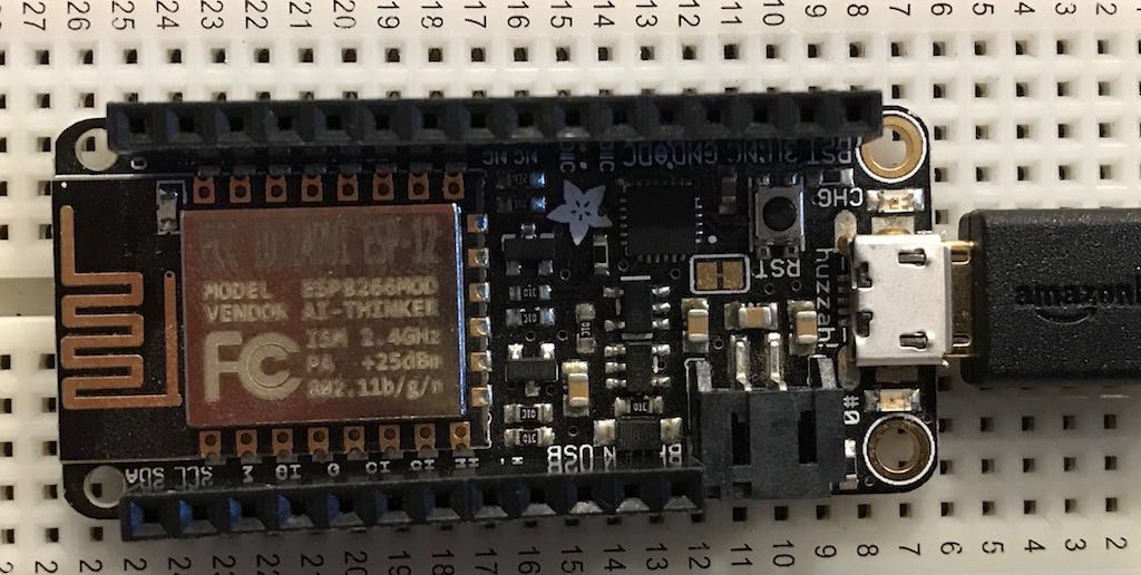
 Feather is a line of thin, beginner friendly development boards from Adafruit. The Feather Huzzah is Adafruits take on an ‘all-in-one’ development board for the popular ESP8266 Wi-Fi chip. It comes with USB, battery charging, and two LEDs built in. In this post, we’ll walk through the ‘hello world’ equivilant for AVR programming–blinky.
Before getting started, we need to select a framework for our appliation. EspressIf, the makers of the ESP8266 chip, provide two standard development frameworks: A Non-OS SDK, and the RTOS SDK. The Non-OS SDK is a proprietary general purpose framework for the ESP8266, while the RTOS SDK is based on the popular open source FreeRTOS kernel. In additional to these frameworks, the open source community has rallied to add support for other popular AVR environments, including the widely known Arduino platform. For our blinky project, we’ll choose to use the Non-OS SDK to gain an understanding for programming a chip using it’s default application framework.
Development environment
For your development environment, I strongly suggest using the wonderful PlatformIO toolkit. PlatformIO provides a uniform environment for programming the Feather Huzzah, and many other microcontrollers. I’ll follow up this tutorial with a guide on configuring PlatformIO.
Non-OS SDK
In order for our application to run, the Non-OS sdk requires three things: a user_config.h header file, a user_main.c file and a function void user_init(). user_init is the default method executed when the chip starts. Here, we can initialize our timers, network connections, and other board features. To get started, create an empty user_config.h file, and a user_main.c file with the following.
#include "user_config.h"

void user_init(void) {
}
Controlling GPIOs
Pins on a microcontroller can be configured as either input or output. Controlling these pins require use of special memory locations known as hardware registers.
The Non-OS sdk provides macros to assist with this process. Unfortunately, the amount of macros for GPIO is overwhelming, and the documentation unclear. Instead of relying on these macros, we’ll be manipulating the hardware registers directly to configure our LED pin for output, and to blink its light.
For our purpose, we’ll require four hardware registers. These are defined in the SDK documentation as:
- Output status register: GPIO_OUT
- Output enable status register: GPIO_ENABLE
- Output enable register: GPIO_ENABLE_W1TS
- Output disable register: GPIO_ENABLE_W1TC
GPIO_OUT will tell us which pins are currently ON and outputting. GPIO_ENABLE instructs the chip to enable a specific pin for output. Once in output mode, GPIO_ENABLE_W1TS turns on specific pins, while GPIO_ENABLE_W1TS turns them off.
The SDK already provides aliases for these registers; however, to be more explicit, let’s define them ourselves in our user_config.h.
#define GPIO_OUT *(uint32_t *)0x60000300
#define GPIO_OUT_W1TS *(uint32_t *)0x60000304
#define GPIO_OUT_W1TC *(uint32_t *)0x60000308
#define GPIO_ENABLE *(uint32_t *)0x6000030C
Blinky
With everything set up, it’s time to get coding. The first thing we’ll do is add another #define in our header file for our pin. We’ll be using pin 0, which is wired up to a red LED on the Feather Huzzah. Ad the following to user_config.h
#define PIN 0
Before we can start blinking our LED, we’ll need to instruct the microcontroller to enable the pin for output. This means writing a 1 in the appropriate bit for the GPIO_OUT registry.
GPIO_ENABLE |= (1 << PIN);
Above, we directly enable output on our PIN through bit shifting. (1 << PIN) creates us a number with a 1 in the PIN position. Given our PIN = 0, it is equivalent to 0b00000001. The second part of the assignment is the |= operator. Known as bitwise OR, we can pass a 1 in the bit we want to turn on, while leaving the rest of the register bitmask unchanged. Therefore, if we had enabled another GPIO pin prior to our LED, our assignment operation would leave its bit unchanged.
Next, we need to define our function which will do the blinking. Above user_init(), define blinker.
void blinker(void *arg)
{
  if (GPIO_OUT & (1 << PIN)) {
    // set gpio low
    GPIO_OUT_W1TC |= (1 << PIN);
  } else {
    // set gpio high
    GPIO_OUT_W1TS |= (1 << PIN);
  }
}
On the first line, we use the GPIO_OUT register to check if our PIN is currently on. The bitwise & uses a bitmask to check the state of individual bits stored in another bitmask. It returns 1 if the corresponding bits are on and 0 if they are off. E.g 00100001 & 00000001 //true. If the bit is on or high, we set it low in our GPIO_OUT_W1TC register. Remember, this register was defined as:
Output disable register
Inserting a 1 into a bit in this register actually disabled the PIN. An important implementation detail to keep in mind. In the case where our PIN bit is off, we set it high by enabling the bit in the GPIO_OUT_W1TS register.
The last thing we need to do is run our blinker function on a timer. The Non-OS SDK comes with software and hardware timer options. For our application, we’ll use the software timer. Start by importing the required headers at the top of the file, and defining our timer.
#include "os_type.h"
#include "osapi.h"

static volatile os_timer_t blink_timer;
Next, extend our user_init function.
void ICACHE_FLASH_ATTR user_init()
{
  GPIO_ENABLE |= (1 << PIN);

  os_timer_setfn(&blink_timer, (os_timer_func_t *)blinker, NULL);
  os_timer_arm(&blink_timer, 1000, 1);
}
In os_timer_arm, we pass our timer as the first argument, followed by the timer delay in milliseconds. The last parameter enables running the timer repeatedly.
That’s it! Our user_main.c should look like the following.
#include "user_config.h"
#include "os_type.h"
#include "osapi.h"

static volatile os_timer_t blink_timer;

void blinker(void *arg)
{
  //Do blinky stuff
  if (GPIO_OUT & (1 << PIN)) {
    // set gpio low
    GPIO_OUT_W1TC |= (1 << PIN);
  } else {
    // set gpio high
    GPIO_OUT_W1TS |= (1 << PIN);
  }
}

void ICACHE_FLASH_ATTR user_init()
{
  GPIO_ENABLE |= (1 << PIN);

  os_timer_setfn(&blink_timer, (os_timer_func_t *)blinker, NULL);
  os_timer_arm(&blink_timer, 1000, 1);
}
Flash your Feather and admire your blinking LED!